Using DEdit to Create Worlds
Welcome to the DEdit overview and tutorial. DEdit is the
tool created by the LithTech team that enabled the
Creating levels is an extremely complex and time-consuming process, and the following is merely the starting point for those who want to learn the basics of building worlds for the LithTech Jupiter engine. If you’ve done game design before on a 3D or near-3D game, you’ve probably worked with tools like DEdit. A separate document will cover ModelEdit, the companion to DEdit, which allows you to create characters and models for your world.
Basic Terms
These terms are relevant to a discussion of DEdit.
Project — A project in DEdit represents the sum of all the resources in the game: all the code, all the textures, all the sounds, all the worlds, and so on. Unlike other world geometry editors, DEdit first opens the project, rather than a world file.
World — When your players walk around in your game, it is a world that they’re standing in. Worlds divide your game up into sections where different parts of the game take place. In other games, these are sometimes referred to as maps, levels, scenes, or episodes. World editing is the primary focus of DEdit and each world is stored in a separate file on the hard drive.
Objects — Simply put, anything a player interacts with that moves, lights up, shoots, growls, or goes into the player’s inventory is an object. DEdit allows you to place any kind of object that your game’s code or the engine’s code can create.
World Geometry — Parts of the world that act as walls, floors and sky are generally made of world geometry. Such geometry is solid, immovable, and generally never changes.
Brush — The basic unit of world geometry. A brush is made up of planes that define its faces, lines that define its edges and vertices that define its corners. You can manipulate either an entire brush at once or any of the vertices, lines, or planes in the brush.
Polygon — A closed plane figure bounded by straight sides. Most of the geometry created in DEdit and used for the LithTech Jupiter engine is one sided. As a result most of the creation process involves working with polygons instead of entire brushes.
Primitive — A simple shape that you can add to the world as the foundation of a more complex shape. Typical primitives are things such as cubes, pyramids, and cylinders.
Prefab — A prefab is like a primitive, but more complex. If you build a street lamp complete with textures and a light source that gives off just the right shade of light, you can select the lamp and its associated source (or any group of objects and brushes inside DEdit) and save it as a prefab. Thereafter, you can copy and paste that streetlamp into your world without having to rebuild the whole object.
Unit — The basis of
measurement in DEdit and the LithTech Jupiter engine. Units don’t equate
directly to real-world values. Instead, the game designers can select a scale
of game units to real-world measurements. As an example, in
Mode — DEdit has several different modes that allow you to change certain elements of your world (i.e. just brushes or just objects) without accidentally affecting others. They’re designed to simplify interacting with your world while editing, so it’s important to choose the right mode for your task.
Processing — When you process your world, DEdit creates a second version of the world with some information removed (parts only you need to know about), and other information added (parts only the game engine needs). Processing is a necessary step you’ll take in getting your world up and running in the game, and is often the first place where you will discover problems with your level.
Texture — In DEdit, textures are used like wallpaper, paint, or plaster to cover the raw plywood of your walls, floors, ceilings, doors and so forth. Without a texture, your brush will appear flat-shaded in the game, almost always with unpleasant results. Just as you wouldn’t want a house with raw plywood walls, you always want to apply textures to the brushes in your level.
LithTech Resource Types
Before starting, you should learn a little more about the structure of the resources that DEdit and LithTech can use in a game. The LithTech Jupiter engine can access and use a wide variety of file types and other resources. The list below is arranged by resource type, and each resource type includes a list of the sorts of files LithTech can use in that type, as well as a description of those files.
Project — As mentioned before, the project is the total of your whole game and all its resources. A .DEP (DEdit Project) file at the top of your tree of game resource directories serves as a guide to DEdit. The .DEP file is a pointer to the rest of the resources for DEdit and includes some of the information about your game resources. The rest of your game’s files exist in subdirectories of the directory where your .DEP file resides.
Directories — The subdirectories that contain your other game resources are a type of resource in themselves. The structure of these directories defines the tree views you see in many of the tabs in DEdit’s Project window. If you find a game’s .DEP file and look at the subdirectories in the same folder with it, you’ll see names such as TEXTURES, WORLDS, SOUNDS, and MODELS. These folders contain whatever resource they’re named for, so if you want to add new textures to a game or copy a world from one game to another, you should look in the directories named Textures and Worlds, respectively.
Worlds — Worlds come in two forms: .LTA files and .DAT files*. If you think of worlds as programs, the .lta file is the source code: Editable and understandable by the user and DEdit, but not executable. The .DAT file is like an actual program: it can be run in the game, but since it’s been “compiled” (processed, in this case), the user can no longer modify it. The .lta files are what you change and save changes to inside of DEdit, and the .DAT file is the output of Processor.exe, which prepares your world to run in the game and optimizes its performance.
*.LTA files can also be saved as .LTC and .TBW files. .LTC files simply .LTA files that have been compressed. .TBW files are a binary representation of the .LTA file. .TBW files load and process faster than .LTAs or .LTCs, so you’ll probably want to save your worlds as .TBW files in most cases.
Textures — LithTech uses its own form of texture, the .DTX file. Textures can be up to 32-bit images, although you can obviously choose to make lower-color textures. The .DTX files also contain flags for additional information used by the engine and the game. You can convert .PCX and .TGA files into .DTX files by importing them inside of DEdit.
Sprites — Sprites (.SPR files) consist of a series of .DTX files linked together as an animation with a set frame rate. They’re commonly used for animations and special effects such as smoke, bullet holes, and liquid droplets.
Sounds — LithTech supports standard .WAV files directly with no custom modifications.
Models — Models in LithTech are in a custom format, the .LTB file. This contains the mesh/geometry for the model and other information used by the game engine. You create these files in an external editor such as Maya or 3D Studio Max, and then save them in the .LTB file format using a plug-in. Use ModelEdit, to modify files in the .ltc format once they’ve been created.
Objects — Also known as Entities, these are objects that programmers construct using code. Some of this code exists in the engine and doesn’t appear in the project directories. However, many objects are created in code written for the specific game. These objects are called game objects (to distinguish them from the engine objects inside the engine code) and are stored in a file called OBJECT.LTO in the same directory as the project’s .DEP file.
Prefabs — A prefab is a collection of objects, both brushes and code objects that are stored in their own .ltc files (just like a regular game world) in a separate set of directories. Anything you make in a level can be exported as a prefab to make it easier to re-use later. Examples are benches, camera systems, hallways, doorways, and statues. Prefabs can be useful if your group needs a way to distribute standard-looking objects to its members.
Setting up the Editor
Once you have DEdit installed you will need to set the proper paths for it to work with the game. Click on DEdit.exe in the Tools directory and set up the following:
At the top of the editor select Edit/Options. This will bring up the DEdit options menu.
The paths are set under the Run tab.
The first box is for the executable and should point to the
Lithtech.exe in the
The second box is where you set your working directory.
The final box is for the program arguments. It is a set of commands for running the game and should be as follows -rez Game +errorlog 1 +runworld %WorldName%
Select ok to close that window. Now you need to open a
project. At the top of the editor select File/Open Project. Browse for your
This should set the editor up for the game. I suggest closing and reopening DEdit after this is complete to save your changes.
Setting up Preferences
Once you have DEdit working with the game you can adjust the preferences to suite your needs. These are also located in the DEdit options menu, which can be found by selecting Edit/Options from the top of the editor. The editor works fine as is, and changes are only recommended if you are having performance problems, or for advanced users who want to adjust their settings.
For better performance you can lower the Number of Undos stored, which can be found under the miscellaneous tab.
Lowering the Default far Z setting under the Viewport tab also has performance benefits. This is the distance the editor sees in the 3D window, the value is in units. This is best left alone if you aren’t working on a large and complex level.
Most of the other settings in the DEdit options menu are for preference.
There is also a list of key bindings with options to change them. This can be found by selecting Edit/Edit Key Configuration from the top of the editor.
The DEdit User Interface
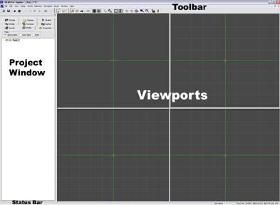
The callouts in this screenshot illustrate the various sections of DEdit’s UI. Use the buttons in the Toolbars to make new worlds, switch modes, and run your world. You can learn an individual button’s function by hovering your mouse over it to get a Tool Tip.
In the Project Window, DEdit gives you access to all of the resources in the game. Most tabs represent a resource you can add to the game. There are two special ones (Properties and Nodes) that relate to objects inside your maps. We’ll discuss all of these in a later section and they’re documented in the DEdit Toolbars chapter as well.
There are four viewports that provide windows onto the world you’re building. Each one presents a different view of the world. The upper left window shows you a Perspective view shot from a movable camera point in the level. The other three views have a fixed-view camera that displays either Top, Front or Left view (going in clockwise order). You’ll spend a lot of time working with these views.
In the Status Bar, DEdit provides information about the level or about the view you’re currently in. We’ll get into the depths of the user interface in later chapters, although you’re welcome to stop and explore if you’d like. Use the Tool Tips and the Status Bar to learn more about what the controls do.
Building a Room
This will be a simple tutorial on building a basic room using the tools supplied with DEdit. Further detail and explanations of the elements can be found after the tutorial section.
Select the Worlds tab on the left side of the editor
in the Project Window and highlight the Worlds folder. From the
toolbar at the top of the editor press the
DEdit is divided by four viewports to work in. You can adjust the grid size in each view by holding the mouse cursor over it and pressing the + and – keys. The grid size is indicated on the bottom of the editor on the status bar. Keep the grid size at 64 units for now. Using the viewport on the top right of the editor. Move your mouse cursor to the top left corner of it and hit the spacebar once. This should have placed a point on the grid and left you with a line that is connected to the point and your cursor (Figure 1.). You can hit the backspace key at anytime in this process to remove the last point.
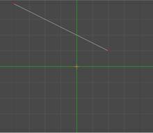 Figure 1.
Now move the mouse cursor to the top right corner of the viewport and hit the spacebar again. You should now have a straight line that draws across the top of the viewport with a point still connected to the cursor. Do this again in the bottom right corner, bottom left corner, and then over the first point you made to make a square. This should conclude your square and a new brush dialog window should pop up asking for a thickness value to make it a cube, 256 units is fine for now. You should now have a cube of some sort that is visible in all viewports (Figure 2.).
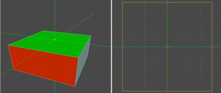 Figure 2.
Holding your cursor over the top right viewport, try holding the O or I key and move your cursor around. The O key will zoom your view in and out (your mouse wheel will also do this), while the I key moves your view along the plane. All three 2D viewports work like this. Move your cursor to the top left viewport, which is your 3D or perspective view. In this view hold down the O key and move your mouse around, this pivots the view from the point where your camera or view position is. If you hold down the O key and press the left or right mouse buttons it will zoom your view in and out. Holding down the I key in this view will allow the mouse to move along a plane, combined with pressing your right mouse button will move it vertically. The U key will deselect an object; you can simply click on the object with your mouse to select it again. With the brush selected you will notice it has handles on the corners, along the edges, and in the center in your 2D views. These are for sizing and positioning the brush. In the bottom right corner of the editor on the status bar there is a readout for the dimensions of the selected brush. By selecting the handles and stretching them in the different 2D views, make the brush measure 512x256x512. On the left portion of the editor in the project window there is a selection of tabs. Select the textures tab and pick a texture to place on the brush. Select a texture from one of the folders in the Prototype directory to apply to the brush. The texture should now show up in a window just below the selection menu. With the texture and the brush selected, press the Apply Texture button on the top toolbar to add this texture to the brush. With the brush still selected hit the F key to flip the normals on the brush. This turns the brush inside out basically so that there is now an interior space.
With the brush still selected press the Marker to Selection button, and then the Center View on Marker button. This should position your view on the space you created. Right click in one of the viewports and select Add/Object, This will bring up a Select Object Type window. From the Class Types menu select GameStartPoint and then select ok, this adds the starting point from where you enter the level when in the game, this is an object.
There are three modes for selecting and working in DEdit: Brush Edit, Geometry Edit, and Object Edit. You will need to press the appropriate button on the top toolbar for which mode you need to be in if you deselect your object at this point. Notice that when adding new objects they appear in the middle of the marker (the big green crosshair looking thing). You can move the marker in the 2D views by holding the X key and moving your cursor, or if you have something selected and you can press the Marker to Selection button to center up on it. At this point if you select the Nodes tab in the project window, you will notice you have two items in your node tree now. You can select from this list no matter what mode you are in. The node tree is a means of organizing your level in a manor that will make it easier to work on, as it grows larger in size and complexity. With the GameStartPoint object selected, move your cursor to one of the bottom viewports and press your down arrow key once.
In your top view using the right arrow key move it two spaces to the right. This will move the selected object one grid space down, which should leave it 64 units (one grid space) above the floor. The arrow keys are an optional way to move items in the editor. With the marker still centered on the brush right click on one of the viewports again and select Add/Object again. This time select the WorldProperties object from the ClassTypes window. The level will now run, but needs a light object placed in it or it will too dark to see anything. With the marker still centered on the brush, right click any viewport and select Add/Object again. From the ClassTypes window select the light object to add a light. Using the up arrow key in one of the bottom viewports, move the light up one grid space. It should now be one grid space from the top. What you should now see is a new box above the old one that is surrounded by a large sphere. The sphere is the radius within the level that the light will fill. Go to the Properties tab in the project window and look at the properties of the light. In most cases and entity’s properties are the most important tool used to control its behavior. In the case of lights, this is where you can change their size, brightness and color. The light’s current size (set in the LightRadius property) is 300. That’s probably a little small, so change the value to 600. In the viewports you’ll see the size of the light radius increase as well. Now it’s large enough to make a good-sized pool of light around the player. Now is a good time to save your level by pressing the Save Project button on the top toolbar. It’s a good idea to save your progress often when working on levels.
Before processing the level, a special brush needs to be added. This brush should be a box that contains all of the geometry and entities in the map. Using the steps above, create a large box shaped brush that easily encompasses the original room. With the brush selected, click on the Properties tab and change the Detail property from True to False. Each map should have a single Detail=False brush containing all other brushes and objects. Failure to add this brush or adding additional Detail=False brushes can result in unpredictable and undesirable behavior in the processed version of the map. It is often best to hide the Detail=False brush while editing and then verifythat it still covers all of the items in the map just before processing. When building a map, it is a good idea to keep a checklist in your mind of items that are essential for the map to process properly. This includes the GameStartPoint object, the WorldProperties object, some form of lighting, and a single Detail=False brush containing all of the other items in the map.
The level is now ready to process and run. Press the Process World button on the top toolbar, when the process window pops up select the Process button and press the Close button when it’s done. To run the world, press the Run World button on the top toolbar.
Adding a Second Room
This tutorial will guide you through the process of adding a second room to your level. This exercise requires that your grid size be set to 64 units in all your viewports.
Select your original brush you created in the editor either in the node tree or by left mouse clicking over it in one of the views while in Brush Edit Mode (found on the top toolbar). Select the Nodes tab in the project window, right click the top folder (Test_1) and select Add Container Node. This will create a new folder in the node tree. Name the new folder Room_1. You can name/rename a folder or item at any time by selecting it in the node tree and pressing F2 or right click the folder and select Rename. With your brush selected right click the new folder (Room_1) and select Move Tagged Nodes Here. This will move your brush into its own folder to make it easier to work with. Do the same with the light object you added to place it in the Room_1 folder.
Center the marker on the geometry that makes up the room. In the perspective you will need to position your view to the interior space of the brush. You will need to be in Brush Edit Mode (top toolbar) to work with the brush and the polygons that make up the brush. With the brush selected press Ctrl + J to disconnect the polygons that make up the brush. This should leave you with six individual polygons. In the 3D viewport select the wall on the right side of the room. If you’re not sure which one it is, keep selecting them until you see the line on the right side of your top right (top view) viewport highlighted with handles on it. With your wall (polygon) selected move to your cursor to the bottom left (side view) viewport. Move your cursor to the top of the polygon and one grid space left of center. Press the spacebar and it should create a point on the grid one space left of center. Move your cursor (making a straight line) to the bottom of the polygon and press the spacebar again. You should now have a straight line that follows one space left of center down your polygon. Press the S key to split the polygon. This is called a two-point split. You should now have a split down the left side of the polygon. In the 3D view select the polygon to the right (the right half of the wall you just split) of the split. With the polygon selected move the cursor back down to the bottom left (side view) viewport and make a split one grid space right of center (two spaces right of the first split) the same way you did the first one. This should leave your wall in three pieces (polygons). In your 3D view select the middle polygon of the wall and move your cursor back to the bottom left (side view) viewport. Your polygon should be two grid spaces wide and the full height of the wall. Grab the handle on the bottom center of the polygon by holding the left mouse button down on it and raise it up three grid spaces. There should now be an opening in the wall (Figure 3. shows 3D and side view).
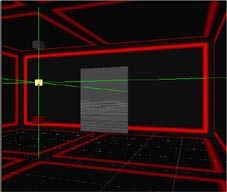
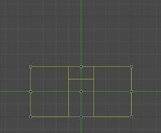 Figure 3.
In your 3D view select all three of the polygons that make up the wall. You will need to hold down the Ctrl key while left mouse clicking each polygon. Holding down the Ctrl key while selecting allows you to select multiple items whether they are brushes, polygons, or objects. With all three polygons selected press Shift + J to connect or join them. You can now select anywhere on the wall and it will select the entire wall. With the entire wall selected move your cursor to the bottom left (side view) viewport and make a horizontal split across the entire wall that runs along the top of the opening you made (two grid spaces down from the top). You can do this the same way you made the vertical splits to create the opening. In your 3D view select all the polygons that make up the wall and join them again by pressing Shift + J. At this point the wall should be made up of five polygons that are joined (Figure 4.).
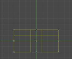 Figure 4.
In the 3D view select the wall again, the whole wall should select with one click since the polygons were joined. You will need to be in Geometry Edit mode for the next operation. With that wall selected press the Geometry Edit button on the top toolbar. Move the cursor to the bottom left (side view) viewport. The door opening is there but the geometry is incorrect. In Geometry Edit mode you will see at the corner of each polygon there is a little dot that highlights when you run the cursor past it, this is a vertex. For geometry to be clean, a vertex should always meet up with another vertex or be on a corner. If it sits an edge instead of another vertex, it creates what is called a t-junction and while the level processes, it will try to fix these on its own. It is better to build clean and avoid making the processor make the decisions on how to cut up the geometry for you. You will also get better lighting results if you build clean. With the wall selected and in Geometry Edit mode, in the bottom left (side view) viewport move the cursor over the vertex that is not in a corner on the left side of the wall (you should see it highlight). Hold down the M key and the left mouse button and drag the vertex up to meet with the one in the top left corner. Now using the same technique grab the top left vertex that meets the ceiling above the door and move it to meet up with the one in the far left upper corner (Figure 5.).
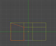
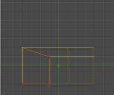 Figure 5.
Do the same thing for the ones on the right side, dragging them to the top right corner. The geometry around the door is now clean. The floor isn’t, but we won’t worry about it for now. At this point you can select all the walls in the room and join them using Shift + J to keep things manageable. You will need to be in Brush Edit (top toolbar) mode to select and join them.
We will now add a hallway. In the project window select the Room_1 folder in the node tree from the Nodes tab to highlight the room and press the Marker to Selection button on the top toolbar. This should center the marker on your room. Using the top right (top view) viewport zoom the view out (using the O key or mouse wheel) enough so that you could fit two rooms in the view. Using the same technique you used to create the first brush (Room_1), create a brush on the right side of the existing room that meets up with its edge and is centered. Make the brush two grid spaces wide and four grid spaces long (128 x 256). When the editor prompts you for the thickness after you connect the points to make the brush, 256 will work for now. You should now have a new brush that is highlighted, but doesn’t sit flush with the door opening. With the brush still selected, move the cursor to the bottom left (side view) viewport and drag the handles so that the new brush is the same size as your door opening. The brush will already have a texture on it since you selected a texture for the first room. At this point move your view out in your 3D window so that you can see the entire room and the hall (Figure 6.).
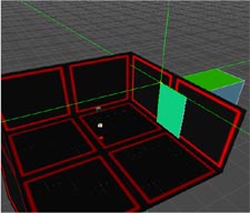
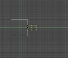 Figure 6.
With the hall still selected, press the semicolon ( ; ) key. This should have hidden everything except for the new brush you created since it was selected. To unhide all just press the apostrophe ( ’ ) key, but keep the other stuff hidden for now. With the hallway still selected press the Center View button on the top toolbar to center up your view on the piece you’re working on. Now press the Geometry Edit button on the top toolbar to go into geometry edit mode. In the 3D view, position yourself at either end of the hallway and hold the cursor over the polygon. You should see the edges of it highlight red when doing this. When all the edges around the polygon are highlighted red, press the Page Down button to delete it (Figure 7.).
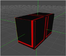
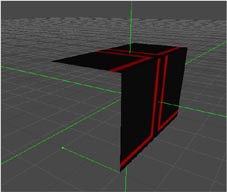 Figure 7.
You can hit Ctrl + Z at anytime to undo your last action, you can also select undo at the top of the editor with Edit/Undo. Delete the polygon at the other end of the hallway the same way. You will now need to go back into Brush Edit mode (top toolbar). Once back in Brush Edit mode, with the brush still selected press the F key to flip the normals (turn it inside out). You should now have a hallway that is open on both ends. Press the apostrophe ( ‘ )key to unhide the rest of the level. In your node tree make another container like you did for the room and name it Hallway. With the hallway selected right click on that folder and select Move Tagged Nodes Here to place the brush in that folder.
Select the hallway and press the Marker to Selection button (top toolbar) to center the marker on it. In the node tree select the entire Room_1 folder, this should select all the geometry and the light object that make up the room. With the entire room selected go to the top of the editor and select Edit/Copy and then Edit/Paste Alternate. This will create a duplicate of that room sitting in the same world space as the original, folder and all. With the entire new room still selected move the cursor to the top right (top view) viewport. While holding down the Ctrl key press the right arrow key four times to rotate the new room into position. When you rotate items, the editor uses the marker center as the rotation center point. With the marker centered on the hallway the new room should rotate around it and sit right into the correct position. If things aren’t set up so handy, you can always rotate off any given point and manually move it into position by dragging it with the mouse, or nudging it with the arrow keys. Now in the node tree rename the new folder to Room_2 by highlighting it and pressing F2, or by right clicking it and selecting to rename it. You should now have two rooms connected by a hallway. Save your work, process it, and run it.
Applying Textures
Applying the proper textures to there surfaces is a key element in making a level feel like an actual place. This tutorial will guide you through some of the texturing basics in DEdit using the level you just created. It will also cover some basics in brush properties.
Select the Room_1 folder from the node tree and press the semicolon ( ; )key to hide the rest of the level. In the 3D viewport, move you camera view inside the room. You will need to be in Brush Edit mode (top toolbar) to start out. Inside the room, select the polygon that makes up the floor. Under the properties tab in the project window there should be some basic properties for this polygon. Select the dropdown for the lighting field and change it to lightmap. On larger polygons such as floors and ceilings changing the lighting to lightmaps will look better, but at a cost. Lightmapping is a performance hit to the engine and should be used sparingly. Select the polygons that make up the ceiling and walls, and do the same thing. Now select all of the walls that make up the room. At the bottom of the editor you will see the room size is 512x256x512. This means that your wall height is 256 units, and the SWSib030 texture that was applied to the room is 256x256 so it fits nicely. Right click in any of the viewports and select Texture/Map Texture Coordinates. This will bring up a new window that allows you to manipulate the texture size and position. The top portion of the window is for adjusting offsets. The wall texture should already fit correctly but feel free to adjust the offsets to see what they do. Just select cancel when you’re done so that the texture remains as it was. Press the U key to deselect any geometry and go into Geometry Edit mode (top toolbar). Explore to Tex/Prototype/M02/Courtney/BinM02X in the Textures tab in the project window, and select the texture M02X_W08. In your 3D viewport highlight the floor by moving the cursor over it, you will see the edges turn red. Press Ctrl + T while the polygon (floor) is highlighted to change the texture to the new texture. Do the same thing for the ceiling using the M02X_W08 texture. You can view all the textures in a set by right clicking on the list and selecting View Texture Palette.
Tip: In Geometry Edit mode you can highlight a texture on a surface by holding the cursor over it and press the K key to have the editor align it for you. You may have to press it a few times since it lines the texture per edge and may not pick the edge you want to use first try. You can also press Shift + C to have it fit the texture to a surface. Note that this will stretch the texture to fit and it may need to be manually adjusted in the Map Texture Coordinates window to adjust it to look proper.
Adding Prefabs
Prefabs are pre-assembled sets of geometry and sometimes include objects such as Lights or worldmodels. Prefabs are a quick way to bring a level to life if they are already made. They are a very efficient way to build for items that are going to be used more that once. Also, you can make changes to a prefab on its own, and it will update the changes across the level/levels globally for that prefab the next time the level is loaded in the editor.
Start with the existing Test_1 level. Select Room_1
from the node tree and hide everything else. Add a container node in the Room_1
folder and name it Prefabs. If you go to the node tree and
highlight the new Prefabs folder and press F3, it will
make this folder the parent folder. The prefabs you add will now automatically
be placed in that folder. If you create an object such as a light fixture or
control panel that will be used repeatedly in your maps, you can select all of
its components and then choose Save as Prefab from the Selection
menu to add it to the Prefabs directory for later use. Try creating a
simple prefab such as a textured cube similar to the Datablocks used in
Adding a Sky
This will be a simple tutorial on adding a skybox to your level. We will be using the Test_1 level for this exercise. Set the grid size to 64 in your 2D views.
Holding the cursor over any viewport press the apostrophe
( ’ ) key to unhide all of your work. You
will need to be in Brush Edit mode for the next step. In your node tree,
select the top folder and add a new container to it. Name this container Sky
and press F3 with the new folder highlighted in the node tree to make it
the active parent folder. In the top view viewport, using the spacebar
make a box around the level that has a one unit space between it and the rooms
all the way around. When you complete the box and it prompts you for a
thickness, 256 units will work for now. Position and size your brush so that
there is a one-unit space between it and the rooms in your side view viewport
(Figure 8.). You will now need to flip the normals on the brush by pressing the
F key while it is selected to change it into an interior space. Your
rooms should now be sitting inside of the new brush. With the new brush
selected go to the Textures tab in
the project window. Explore to the root
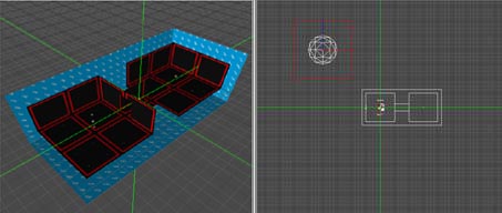 Figure 8.
In the top view viewport zoom your view out a bit using the O key or the mouse wheel. Move your marker using the X key so that it is positioned outside of your level (the rooms). Create a 512x512x512 unit box-shaped brush, flip the faces with the F key so that they face inward and then apply a texture of your choosing. With the brush selected, press the Marker to Selection button to center the cursor at the brush’s center, right-click, choose Add Object and add a DemoSkyWorldModel. In the Nodes tab, highlight the new brush and then drag it underneath the DemoSkyWorldModel. This action binds the brush to the DemoSkyWorldModel so that it inherits the properties of its parent. Select the DemoSkyWorldModel, click on the Properties tab, click on the SkyDims field and then change the dimensions to 256x256x256. This will expand the DemoSkyWorldModel so that it just encompasses the brush. The size of the DemoSkyWorldModel can be further adjusted by selecting it, going into Object Edit Mode by pressing Ctrl + H and then resizing the DemoSkyWorldModel in the same manner that you would a brush. Add a light to the center of the DemoSkyWorldModel to light the brush. Increase the light radius to 600 so that the brush is completely illuminated. These steps allow you to create a simple sky. To save time when building maps, try adding all the elements used to create the sky except the sky portals to a single node and then use the Save As Prefab option. To view the sky, disconnect the polygons of one of your rooms by pressing Ctrl + J, delete one of the wall polygons to create a window and then process the map. The sky should be visible outside through the window when the map is run.
Adding Basic AI
The TRON 2.0 AI systems are highly advanced and rather complex. Adding a complete set of AI that will behave
in a realistic fashion under all conditions is beyond the scope of this
document. However, the basics of adding
AI are simple. This section will show you how to add a single patrolling AI
that will attack when it sees the player.
First, load the Test_1 world, and then save it as Test_2. Then, select Room_2 from the node tree and hide
everything else. Next, add an AIRegion object and place it somewhere in the
room. It’s exact location is not important. Now add an
AIVolume object at the center of the room, and expand its size until it almost
fills the horizontal dimensions of the room without actually intersecting with
any walls. Note that the AI use these Volumes to determine where they are allowed to go,
so AI volumes that intersect with walls can allow the AI to walk right through.
When done, click on the properties tab, and type AIRegion0 in the Region field.
Now that the volume is placed, add 2 AINodePatrol objects to the level and place them at opposite ends of the room. Make
sure that the nodes are positioned within both the horizontal and vertical
boundaries of the Volume, or the AI will not be able to reach them. At this point, you must modify the Next property of each node so that they point to each other (i.e.
AINodePatrol0 points to AINodePatrol1 and vice versa).
Now that the AI environment has been established, it’s time
to add an AI. From the World menu, select Add Object, then click on CAI from the object menu, and then select CAIHuman. Make sure that the AI is placed somewhere within the horizontal
boundary of the AIVolume, or it will not be able to move when you run your
world. When it’s in position, click on the Properties tab. For ModelTemplate, type in or select IC_Regular. For Brain select ICRegular. For GoalSet, select ICRegularPatrol. Finally, Next, click on the Attachments property, and select ICRegularDisc from the RightHand field. When done, click on OK to close the
attachments window.
To learn more about working with
AI, see the
Creating Multiplayer Levels
Disc Arena and Disc Tournament
-Each map should have four separate arenas and a spectator area.
-Each arena should have a single Arena object at its center. It’s usually best to follow the naming convention of Arena_01, Arena_02, etc. If you have items that change during each match such as disappearing platforms or keyframed objects, a message should be sent to reset them to their original state after each point. The best way to do this is to put all of the reset commands into a single Trigger and then activate the Trigger by adding a message to the OnPointEnd field of the Arena object (i.e. “msg Arena1Reset trigger”).
-Each arena should have at least four ArenaStartPoints for each team. After adding an ArenaStartPoint, its Team and Arena can be specified in its properties by using the Type and Arena fields, respectively. In addition to the four ArenaStartPoints for each team that are in the Arena, four more ArenaStartPoints should be added in the spectator area for each team. The spectator ArenaStartPoints can be anywhere in the spectator area but it’s usually best to put them near the window that overlooks the arena in use. That way, when people respawn in the spectator area, they can easily watch the remainder of their team’s point. To create the spectator ArenaStartPoint, just set the Type field to Spectator and the Arena field to the appropriate arena.
-Each map needs to have a text file named “mapname”info.txt (without the quotes) in the same directory as the map. This text file defines the subroutines that will be available in the map. A sample is provided in the samplemaps.rez which can be copied and renamed to your map name. For example, if you’re making a new Disc Arena / Tournament map called Tronolith.dat, you would save the map to C:\Program Files\Buena Vista Interactive\Tron 2.0\Game\Worlds\RetailMultiPlayer\DiscArena. You could then make a copy of DiscArena01info.txt (from samplemaps.rez) and rename it to Tronolithinfo.txt.
-If you would like to eliminate falling damage from the game, this can be accomplished by creating a large brush that fits around the world and binding it to a SafetyNet object, which is a form of VolumeBrush. Similarly, if you want to make an instant kill brush for bottomless pits, it’s best to create a VolumeBrush that administers damage, such as the EndlessFall type, with a negative value (-1000) to instantly kill any player that enters it. Please note that the SafetyNet and EndlessFall brushes should not intersect, but should instead be adjacent to one another.
Lightcycles
-Lightcycle arenas should be set up so that all of the action occurs on a single plane. When a Lightcycle makes contact with a wall, another lightcycle or another lightcycle’s trail, it will be destroyed.
-At least eight GameStartPoint objects with their GameType set to MuliplayerLightcycle should be added to the map. They should be at least 128 units above the ground plane and be evenly spaced to give all players equal advantage. Each GameStartPoint should have “msg MPStart trigger” entered in its command field. See below for details.
-A number of Spectator objects should be placed in the map to provide good vantage points for players who have either been defeated or have not yet joined teams.
-Two triggers should be added to regulate any objects used to provide gameplay during a match such as powerups, speed zones or other obstacles. These types of items should be initialized at the start of each point. To do this, create a Trigger called MPStart. If the GameStartPoints are set up correctly, this Trigger will be activated at the start of each point. Messages can then be added to MPStart to activate any powerups, speedzones or obstacles that should be active during the point. Similarly, another trigger should be added named LANClean. This trigger is activated automatically by the game when the point is won and it can be used to remove any powerups, speedzones or obstacles so that they are correctly initialized when the MPStart trigger sends out its message at the start of the next point.
The steps above are the minimum required to create a custom multiplayer map working. Once the basics are set up, an infinite number of combinations can created by just using new geometry or textures or by integrating other game objects.
Lighting Basics
Working with Light Colors
A property you may want to modify is the light’s color. To change the colors, click on the color sample button next to the property name. Start by clicking the white button (LightColor). The dialog that comes up is a standard color picker dialog, and it allows you to pick from a standard palette or create your own custom colors. Choose one of the very light blue colors for something similar to a fluorescent light. You can use the slider on the far right to lighten or darken the color to your taste. When you’re done, close the dialog and you’ll see your new color in place on the LightColor button. Lastly, you can set the brightness of the light using the BrightScale property. At its default setting of 1.0, the light appears at a normal brightness. If you change the value of BrightScale to 0.5, the light’s brightness is halved. However, the radius stays the same. Thus, you can create a very large light that doesn’t overwhelm the area closest to its center. Likewise, if you want an intensely bright light, you can increase the BrightScale value to 2.0, which will make the light much brighter. For now, leave BrightScale as it is.
There is another useful type of light with very different behavior from the regular one: The DirLight. While a normal light throws light in a sphere all the way around it, a DirLight acts like a spotlight: It throws light in a cone, the diameter of which you can control.
The Dirlight
A DirLight is a directional or spotlight. You can aim a Dirlight using the object’s Rotation property. Click the button next to the property’s name and you’ll see a dialog appear. Within this dialog, you can control every aspect of the object’s facing. Each of the three aspects has a range between 0 and 359. Yaw controls the horizontal facing of the object, and is aligned identically to the Top viewport like a compass needle. You can use the preview display at the top of the dialog to see how the results will appear. A setting of 0 points the object straight “north,” towards the top edge of the Top viewport. A setting of 90 would aim “east,” a setting of 135 would point “southeast” towards the lower right corner of the viewport and so on. For now, set the yaw to 180 to spin the Dirlight around so it’s facing the opposite direction.
Pitch controls the vertical angle of the object. The Pitch preview display shows the result of your changes. Since the Dirlight is pointed at the proper angle already, there’s no need to change this.
The Roll control controls the spin of the object. This is useful mainly for props or cameras, where you want the object to bank or its viewpoint to sway.
World Ambient Light
You can add an overall ambient light value to your entire level. In the editor press Ctrl + W to bring up your World Info window. Enter AmbientLight R G B in the field with the R G B being light values for Red, Blue, and Green. An example for this would be AmbientLight 12 12 12. This would give the level a dim overall lighting with white light since the RGB values are all equal. It isn’t recommended to light the entire level like this without using the light objects. The world ambient lighting does not cast shadows and will give the level a flat overall look when used on it’s own.
Lighting Properties on Brushes
With a brush or polygon selected, you can change the way it is effected by lights in two ways. In the Lighting field generally Lightmap or Gouraud will be used for the basic lighting style. Gouraud lighting takes the light sample from the vertices to light the brush. This is the preferred method to light the majority of your world. On larger brushes or where a vertex meets an edge the results may not look very good. Keep in mind where your vertices are when placing lights in your level, and try to place the light source near them. Lightmapping creates better looking results on larger planes, but at a cost to perfomance. When a polygons is set to Lightmap you can optionally change the lightmap grid size. This can be found in the LightControl field. By selecting it, it will open a new dialog with a field in it named LMGridSize. The default value for the field is 20 and the shadows become more defined as the variable is decreased. Note that halving the value makes a quadruple hit to the performance. It is recommended only to decrease the value in isolated instances. Generally a value between 6 and 10 will give you a pretty defined shadow where you feel it may be necessary.
Glass
To create glass, simply bind a brush with a glass texture to a WorldModel object and adjust a few fields under the Properties tab in the Project Window. Set the DebrisType to Window, the SurfaceOverrride to Glass, and the BlendMode to Translucent. The Alpha field dictates the opacity of your glass, with 1.0 being opaque, decreasing the value makes the glass more transparent. Generally the Alpha on glass is set to about 0.5.
Occlusion
An occluder is a plane with the brush Type set to Occluder. Occluders are most effective when they are axis aligned (not set at an angle), it is not recommended to place them otherwise. Occluders are placed to block the engine from drawing geometry that is not visible to the player, thus reducing the number of triangles drawn by the engine. The geometry of a level is divided into renderblocks, with each renderblock containing 2,000 triangles. Any geometry that is associated with a worldmodel will draw it’s own renderblock regardless of the number of triangles within it. If a renderblock cannot be seen by the engine from the players perspective the geometry contained will not be drawn by the engine. When possible it is best to run them a good distance through the geometry if they lead to an area where the player couldn’t see in game anyways. This will assure they cover as many renderblocks as possible. Occluders do eat up resources at runtime, so the should be used sparingly and efficiently. Small occluders are not very effective since the majority of renderblocks are rather large and would not be hidden behind them. There are two types of occluders, dynamic and static.
Static Occluders - Static occluders are always on and occluding the geometry behind them. They are best suited placed in walls, ceilings, and other larger pieces of geometry, which the player could not see through anyway. If a static occluder has bad placement it is most likely you will see geometry popping in and out when running the game.
Dynamic Occluders - Dynamic occluders are set-up to work in conjunction with a volume. When a player is in the volume the occluder is active, it becomes inactive when the player leaves the volume. The dynamic occluder is valuable to hide large sections of geometry when the player is in an area where the geometry is not visible anyway. To make a dynamic occluder volume you can just create a brush that you want to act as the volume. Center the marker on the brush and right click any viewport and select Add/Object, from the Class Types menu select and add the DynamicOccluderVolume object. Select the brush you created for the volume, and in the node tree place the brush under the DynamicOccluderVolume object. With the DynamicOccluderVolume object selected go to the Properties tab in the project window. Notice there are fields for occluder names. Enter the name of the occluder/occluders you want to be active when the player is in the volume in these fields. It is best to give the dynamic occluders special names to make them easier to keep track of when using them. You can rename them in the node tree, and example would be Dynamic_01.
Objects
Below is a list and basic description of game objects used
in the creation of
AIInfoVolume
Volumes placed to send information to the AI when a player is within the boundaries.
AINode
Nodes placed to relay information or instructions to the AI.
AIRegion
Objects used to group the AI volumes into regions of a level. This divides the level into unique areas for the AI’s search behavior.
AIVolume
Volumes placed for areas the AI can travel in. Some have special attributes to inform the AI of actions to take while in the volume.
AmbientOverride
You can assign an ambient value to brushes that are placed under this object in the objects properties. Note that individual brush ambient values are ignored when under this object.
AmmoBox
AmmoBoxes are placed in the world as a powerup. Each Ammobox
can contain up to ten different kinds of ammunition. This item was not used in
Archive Bin
Archive Bins are placed in the world as a means for the player to acquire subroutines or e-mails. Each item can have a separate energy and permission set requirement.
Arena
The Arena object is used to identify one of the four arenas for Disc Tournament and Disc Arena. Typically one Arena object is placed at the center of each Arena.
ArenaStartPoint
ArenaStartPoints are
placed in the multiplayer Disc Tournament and Disc Arena maps to identify
points where players will spawn into the world.
Binary Bit
The BinaryBit object is a multi-purpose switch of sorts that can be used to trigger events, open doors or send any type of message. A permission set required for activation can be specified.
BuildNote
BuildNote objects can be aquired by the player to increase Jet’s version number.
CAI Human
This is the object used to place AI in a level.
Camera
Cameras show scenes in the world outside the player.
CameraPoint
Camerapoints are used to provide points to move the camera to during cinematics.
CinematicTrigger
This is a controller object used for cut scenes and in game dialog.
ClientLightFX
ClientLightFX allow for the quick creation of complex dynamic lighting effects. However, dynamic lighting must be enabled for these effects to be visible.
CommandObject
Objects placed to execute, track and time a series of events and/or commands.
Controller
This object controls properties of up to 8 objects.
CThorne
CThorne is a special object used to create the Thorne character during cinematics.
Decal
An object to place decal textures under, allowing textures with an alpha channel to be placed overlapping standard textures.
DecisionObject
An object placed to give the player multiple choices they can make.
DemoSkyWorldModel
DemoSkyWorldModels allow objects to render in the skybox in a single step. A DemoSkyWorldModel is an object that fuses a WorldModel and a SkyPointer. By doing this, binding a brush to the one object allows it to be rendered in the skybox without the need for any additional objects.
Dialogue
An object placed to message dialogue for the AI to use.
DirLight
DirLights act like a spotlight, shining only within an arc that you specify instead of in a sphere like a regular light. You can aim them to any angle you choose.
DisplayMeter
This is an incremental colored bar meter displayed on the screen. It is useful for “boss” fights.
DisplayTimer
This object displays a timer on the screen in game.
DynamicOccluderVolume
The object used to create a volume by placing a brush under it. When the player is in the volume, the occluders indicated in the volume will be active
EdgeGenerator
This object can be used to bevel polygonal faces. In
practice, it was rarely used in the creation of
EventCounter
This object will store up to 5 different "events", with each event containing an integer value and two commands. The idea is that the game code can increment/decrement the EventCounter's value (by sending ”Increment” or “Inc” and ”Decrement” or “Dec” messages). When the counter’s value is equal to one (or more) of the EventXValue (i.e., Event1Value, Event2Value, etc.), either the EventXIncToValCmd or EventXDecToValCmd will be processes. In other words, how the counter gets to the EventXValue determines which command is sent. For example, if Event1Value = 2, and the EventCounter’s staring value is 0, if the EventCounter gets 2 “Inc” messages, the Event1IncToValCmd will be processed. If at this point the “Inc” message is sent again (so the counter is now at 3), and then the “Dec” message is sent to the counter, the Event1DecToValCmd will be processed. This object also understands the “Lock” and “Unlock” commands (Inc/Dec don’t have any effect on the counter if it is locked).
Explosion
This is an object used to place explosion effects in the world.
Fire
This is an object used to create fire effects.
GameStartPoint
This is the point that the player enters the game world.
GearItem
This is an object used to place gear power up items in the world.
Group
This is an object used when you wish to send the same message to several different objects at once. It acts as a simple relay.
InfoString
The InfoString object causes a line of text to appear on screen when the player’s targeting reticule is trained on the object. For the string to be valid, it must be contained within the cres.dll.
InsideDef
This object was not used in the creation of
IONode
This object was used for the IONode dialogue scenes in
JumpVolume
This object was not used in the creation of
Key
This is an object used to define a point in the path of a keyframed object.
KeyFramer
This is an object used to define a point in the path of a keyframed object.
Light
This is a basic point light, or omni light object used to light the world.
Lightcycle
The Lightcycle object is used to create enemy AI Lightcyclists.
LightcyclePowerup
This object is used to place Lightcycle powerups in the world.
LightcycleVolume
Similar to an AIVolume, the LightcycleVolume defines where Lightcycle AI can navigate in a map. Unlike regular AI volumes, these volumes define the areas that Lightcycles should not go. For example, if you build a map with a column sticking up in the center, a LightcycleVolume should be placed around it to prevent the Lightcyle AI from colliding with it. These volumes should be placed parallel to the groundplane and flush with it.
LightcycleVolumeCascader
When triggered, this object starts triggering the nearest Volumes, moving outward at a fixed rate.
LightGroup
This object was not used in the creation of
Lightning
This object was not used
in the creation of
ModItem
This object was not used in the creation of
NodeLine
This object was not used in the creation of
ObjectiveSprite
This object was not used in the creation of
ObjectLight
This is a light that only affects models.
ObjectRemover
ObjectRemover contains several "groups" of objects. For each group, you may list up to 10 objects. Specify how many groups of objects you wish to keep in the "GroupsToKeep" property.
On the first update, the ObjectRemover will randomly select the groups of objects it will keep (based on how many were specified to keep), and remove all the objects in all the other groups, and then remove itself.
Optimizer
The Optimizer provides a means to upgrade a subroutine to the next level. Optimizers can be keyframed to follow paths or stationary.
OutsideDef
This object was not used in the creation of
ParticleSystem
Any time you want to spawn a large number of similar simple objects in one location or area, you probably want a ParticleSystem object. Particle systems create a cloud of objects, usually sprites or simple models. They can make the sprites move, determine the area where they appear and how long they remain after being created.
PatchRoutine
This object provides a way for the player to replentish Health or Energy.
PlayerLure
This object allows the player to be keyframed while still maintaining some degree of control.
Point
This object was not used in the creation of
PolyGrid
A polygrid is a grid of triangles that can have an animating surface. They’re used to simulate flags, curtains, water, force fields and many other effects.
PolyGridModifier
This object was not used in the creation of
Prop
The Prop object is used to place .ltb models into the game world. Props are typically things that would be too complex or impractical to be created from world geometry. Examples would be plants, telephones, detailed furnishings, etc.
PropType
This object is a subclass of the Prop object. This is a different way of managing prop placement in levels. We found that a lot of the props that we placed were set up the same as each other. Yet we still had to set all of the flags. The PropType object places props by way of a simple dropdown menu. The dropdown menu refers to a bute file where the all of the prop flags have been predefined. Since it is a subclass of the Prop object, it shares many of its properties.
RandomSpawner
The RandomSpawner is used to spawn objects randomly through multiple Spawner objects.
RenderGroup
Items placed under this object can be triggered to hide and unhide from within a DynamicOccluderVolume.
RotatingWorldModel
These are objects that spin on any given axis. The most common example of a RotatingWorldModel would be a spinning fan.
ScaleSprite
ScaleSprites are free-standing textures that don’t need a surface to appear on. ScaleSprites get compounded into a lot of other game objects, but they can be used on their own to make a lot of things happen too. ScaleSprites are used for all kinds of things — halos around lights, floating symbols, decals on walls and objects in the sky.
ScreenShake
The ScreenShake object shakes the camera when triggered.
SecRezzerPoint
ICs will spawn at these points when the SecRezzer alarm is activated.
SkyPointer
SkyPointer objects allow the objects that they target to render in the skybox of the level. Only WorldModel-derived objects and Sprites can appear in the skybox.
SoundFX
This object allows you to place sounds in the world.
Spawner
This is a generic object used to “Spawn” objects into the game world.
Speaker
This object is used in conversational dialogues in a cinematic trigger. If a character needs to have a conversation with a non-AI object such as an intercom, this is the object that will fill the position of that AI in the conversation.
SpecialFX
This object allows of the quick creation of certain special effects.
SpectatorObject
SpectatorObjects define viewing points for multiplayer Lightcycle players who have either not yet joined teams or been derezzed.
Sprinkles
This object was not used in the creation of
StartupCommand
Placed in a level to give commands to objects within the level when the level is loaded.
StaticSunLight
The StaticSunLight object supplies levels that have a skybox with light from a sunlike source. The light radiates into the level through all skyportal brushes as if from an infinitely far point. This sunlight’s direction is determined by the rotation of the StaticSunLight object. Its position doesn’t matter, since the emitted light acts as if it comes from an infinite distance. The StaticSunlight’s position is ignored.
Steam
The Steam object is a form of the ParticleSystem object that has been set up to more easily create particle effects resembling jets of steam. The effect created by this object travels down the forward facing vector of the object.
TeleportPoint
This object is used to define the position and rotation of a point in space that the player or an AI can be moved to instantly.
TextureFX
This object
was not used in the creation of
Trigger
Triggers are placed in a level to send messages or commands to other objects when a player or AI enters or passes through them.
ExitTrigger
This object is a subclass of the Trigger object. This object is used to trigger the end of a level.
TronTurret
This object is a turret-style AI that was keyframed to create the Tanks.
VolumeBrush
Volume brushes are used for a number of effects — Water, damaging environments, ladders, and to relay physics instructions such as gravity changes to name a few. A VolumeBrush object is designed to bind to a brush and use the brush to determine its area of effect. If the effect is continuous, such as snow, it only occurs within the space defined by the brush. If the effect happens to players and AI’s, it only happens to them when they’re within the volume. The effects of the volume are triggered when the player enters the space and usually un-triggered when they leave.
VolumeEffect
Used to place ScatterVolumes and SnowVolumes.
WeaponItem
This is an object used to place Weapon power up items in the world.
WorldModels
General
The naming convention should be mentioned first. There are three basic types, WorldModels, Doors, and Switches. Each of these three basic types has different movement types as prefixes describing how they behave. “Rotating” means the objects will rotate around a point a specified number of degrees around each axis (much like the NOLF HingedDoor). “Sliding” objects will move a specified number of units in a specified direction (much like the NOLF Door), think of the behavior of a desk drawer. “Spinning” objects will spin around a point in a specified number of seconds on each axis (much like the NOLF RotatingWorldModel), think of a ceiling fans behavior. Each movement type has identical properties and behaves exactly the same so when you are learning how to use a RotatingWorldModel you are also learning the RotatingSwitch and RotatingDoor. However, even though a RotatingWorldModel can be used exactly as a RotatingDoor you should NOT put a RotatingWorldModel where a Door should go, and vice versa. Use a Door only for Doors, use Switches only for Switches, and WorldModels for everything else. Game objects, specifically AI and Players, need to know if they are interacting with a Door, Switch or something else.
Most basic functionality is shared for every new WorldModel object. All of the new objects have common features and properties that you can edit. They are all created the same way, they all move and rotate based on their local coordinate system and they can all receive certain messages. “Active” WorldModels, that is any Rotating, Sliding or Spinning objects, can also send commands to other objects and play sounds depending on what state they are in.
Creation
To create an instance of a WorldModel just bind a WorldModel object to a brush or a set of brushes. There are several property values you can edit to achieve the object you want. BlendModes is a property drop down list containing several blend operations for your WorldModel object. WorldModels can have Additive blending, they can be Chromakeyed, or they can be Translucent. None is the default BlendMode for newly created WorldModel objects. You can also edit several other properties such as visibility and solidity. If you have a fairly complex brush that the player will be walking on or moving around you may want to set the BoxPhysics flag to FALSE. You can override the surface flags set by the texture mapped to the brush(s) by simply selecting the desired surface in the SurfaceOverride property dropdown list.
Once a WorldModel is positioned and behaves as you would like you can rotate it by selecting both the object and all brushes it is bound to then select Rotate Object in the right click menu in DEdit. You can rotate the WorldModel on all axis, and in any direction. The WorldModel will now move or rotate with the same behavior around its own local coordinate system.
Damage
All WorldModels can handle damage. Each one has a subset property labeled DamageProperties. There are several different values and flags that can all be edited to define how the WorldModel behaves when damaged. Here is a list of the properties that are included in the DamageProperties subset and what each on means:
- HitPoints: Number of hit points the WorldModel has when created.
- MaxHitPoints: Max number of hit points the WorldModel can ever have.
- Armor: Amount of armor that the WorldModel has when it is created.
- MaxArmor: Max amount of armor the WorldModel can ever have.
- DamageTriggerCounter: How many times the object must be damaged before the damage message will be sent.
- DamageTriggerTarget : Name of the object that will receive the DamageTriggerMessage.
- DamageTriggerMessage: Command string that is sent when the WorldModel receives damage from any source.
- DamageTriggerNumSends: Specifies how many times the damage message will be sent.
- DamageMessage: Command string that is sent to the object that caused the damage.
- DeathTriggerTarget: Name of the object that will receive the DeathTriggerMessage.
- DeathTriggerMessage : Command string that is sent when the WorldModel has been destroyed.
- PlayerDeathTriggerTarget: Name of the object that receives the PlayerDeathTriggerMessage.
- PlayerDeathTriggerMessage: Command string that is sent when the player destroys the WorldModel.
- KillerMessage: Command string is sent to the object that destroys this WorldModel.
- CanHeal: Toggles whether the WorldModel can be healed.
- CanRepair: Toggles whether the WorldModel can be repaired.
- CanDamage: Toggles whether the WorldModel can be damaged.
- Mass: Sets the mass of the WorldModel within the game.
- NeverDestroy: Toggles whether the WorldModel can be destroyed.
Attachments
All WorldModels can have attachments (you can attach models, props, and other WorldModel objects) much like Doorknobs in the NOLF Doors. When attached to a WordlModel, objects will move and rotate with the WorldModel. To have an object attach to a WorldModel when the game loads, add the object you want to attach and position it in DEdit. Enter the name of the Object you want to attach in the Attachments property field, you can have as many objects attached to a WorldModel as you want. List all the objects you want attached separated by a semicolon (ex. Prop1; Prop2; SlidingWorldModel0). During runtime of the game you can attach and detach objects through messages.
States
All “Active” WorldModel objects (Rotating, Sliding, and Spinning) have different states they go through. These states are: PowerOn, On, PowerOff, Off. Doors have similar states with different names: Opening, Open, Closing, Closed. By default, this can be changed in the Options property subset, all objects start in the ‘Off’ or ‘Closed’ state. When positioning and rotating the object in DEdit you are setting its ‘Off’ position. By entering in values for the Movement or Rotation properties you are setting how and where the object will move to when fully ‘On’ or ‘Open’. Sliding WorldModel objects will be moving in the direction you specified while in the ‘PowerOn’ state and when they have moved to the distance you specified they are considered ‘On’. While moving back to their original position and rotation they are in the ‘PowerOff’ state and when they have reached their original position and are at rest they are considered ‘Off’. Rotating and Sliding objects will stay still in their ‘On’ positions and rotations, but SpinningWorldModels will continue to spin at the specified rotations per second while ‘On’.
All WorldModels can receive “ATTACH” and “DETACH” messages sent from other objects. To send an ATTACH just send a message to a WorldModel like you would other objects and enter the name of the object you want to ATTACH:
(Ex. msg WorldModelName (ATTACH Prop0)). Only one object can be attached at a time using this method. When another ATTACH message is sent to the same WorldModel the first attachment is detached and the new object is attached. To detach the object you attached with an ATTACH message, send the object a DETACH message. DETACH takes no additional parameters.
(Ex. msg WorldModelName DETACH)
All “Active” WorldModel objects (Rotating, Sliding, and Spinning) can also receive messages to turn ‘On’ and ‘Off’. Messages that “Active” WorldModels can receive are:
- ON: If not already in the On or PowerOn states, puts the WorldModel in the PowerOn state.
- TRIGGERON: same as ON
- OFF: If not already in the Off or PowerOff states, puts the WorldModel in the PowerOff state.
- TRIGGEROFF: same as OFF
- TRIGGER: Toggles the state. Basically the same as when a player presses use against this object. If the WorldModel is in the ‘On’ or ‘PowerOn’ state it will immediately switch to ‘PowerOff’. If it’s in the ‘Off’ or ‘PowerOff’ state, then it will switch to ‘PowerOn’.
- LOCK: Locks the object. Once locked the object cannot be activated.
- UNLOCK: Unlocks the object so it can now be activated by the player and messages.
These messages take no other parameters so an example to toggle a SpinningWorldModels current state would be: msg SpinningWorldModelName TRIGGER
Options
All “Active” WorldModel objects (Rotating, Sliding, and Spinning) have several options that can be changed in the Options property subset group. These control how interactive the objects are and set some behavior. PlayerActivate and AIActivate, these let the object know who, if anybody, can turn them ‘On’ or Close them. If these are FLASE then only other objects can interact with it by sending it messages, if PlayerActivate is TRUE then a player can trigger the object by pressing “use”. StartOn, when TRUE, puts the object in the PowerOn or Opening state as soon as the game loads. TriggerOff toggles weather or not the object can be turned off. RemainOn, if TRUE, will keep the object in its’ ‘On’ state until told to turn off, either by the player or another object. Locked, when TRUE, will start the object off as being locked. While Locked the object cannot turn on or off until it is unlocked through a message. Waveform is a dropdown list of movement types that the object will use to rotate or move.
Commands
All “Active” WorldModel objects (Rotating, Sliding, and Spinning) can send commands based on what state they are in. There are 5 commands listed in the Commands property subset group: OnCommand, OffCommand, PowerOnCommand, PowerOffComand, LockedComand. Doors have similar commands with different names: OpenCommand, ClosedCommand, OpeningCommand, ClosingCommand. Each command line can have multiple commands, separated by semicolons, entered and each one will be executed every time the WorldModel object first enters the corresponding state. To have a command executed as soon as on object is activated, either by the player pressing “use” or by receiving an ‘On’ message, simply enter the command in the PowerOnCommand or OpeningCommand line. If you would like a command executed at the end of an objects movement or rotation enter it in the OnCommand line. The LockedCommand will be executed if the object is locked and a player or message tries to activate it.
Sounds
All “Active” WorldModel objects (Rotating, Sliding, and Spinning) can play sounds based on what state they are in. There are 5 sounds listed in the Sounds property subset group: PowerOnSound, OnSound, PowerOffSound, OffSound, LockedSound. Doors have similar sounds with different names: OpeningSound, OpenSound, ClosingSound and ClosedSound. Other properties that can be edited in this subset group are the relative sound position, the radius the sound fades off to and weather or not the sounds will loop. The LockedSound will never loop. Each sound is a single .wav file that is easily picked through a browser. The sounds will start playing every time the WorldModel object first enters the corresponding state. To have a sound start playing every time the object starts to turn off or close enter it in the PowerOffSound or ClosingSound. The LockedSound will play if the object is locked and the player or a message tries to activate it.
Animated Lightmaps
All “Active” WorldModel objects (Rotating, Sliding, and Spinning) can have animated lightmaps associated with their movement or rotation. To create animated lightmaps you must first add a KeyframerLight object. Set the properties of the KeyframerLight as desired, position it close to the WorldModel object you would like to lightmap, if it’s a directional light then make sure the light is pointed in the right direction. Setting ShadowMap to FALSE typically looks much better. Once the KeyframerLight is set just type the name of the KeyframerLight object in the ShadowLights property. You can enter up to 8 lights in the ShadowLights property separated by semicolons. Now just enter the number of frames you would like have in the animation, up to 128. Sometimes less frames actually look better but experiment and use what works best. Remember that the more animations and the more frames in the animations is a real memory hog. Too many animated lightmaps is also a real frame rate killer!
WorldModel
Features
This is the basic “non-active” WorldModel object. It does not move or rotate, does not play any sounds and cannot execute any commands. Like all of the new objects this can handle Attachments, can have BlendModes, has Damage properties, and a surface type can be selected.
Use
Any place where you need a stationary WorldModel, this is the object you should use. An example would be a desk that you want to damage or to be able to handle attachments. This object is also very well suited for keyframing. If you want a keyframed WorldModel object you should use this object.
Creation
This object is created normally. Simply bind this object to a brush or groups of brushes and then edit the properties as fit.
Damage
This object can handle damage. Edit the DamageProperties subset to define behavior.
Attachments
This object can handle attachments. Enter all the objects you want attached to the WorldModel, separated by a semicolon, in the Attachments property.
States
None – This object does not move or rotate so there is no need for states.
Messages
WorldModels can receive these messages.
- ATTACH: Attaches the object specified in the message
- DETACH: Detach the object attached with the ATTACH message.
Options
None – The player and AI cannot activate this object. It has no movement or rotation properties.
Commands
None – This object cannot execute any commands.
Sounds
None – This object cannot play any sounds.
RotatingWorldModel
Features
This WorldModel can rotate around a point a specified number of degrees around each axis. The player can interact with this object or it can be controlled only through other objects. Sounds can be played and commands can be executed when certain states are reached. Like all of the new objects this can handle Attachments, can have BlendModes, has Damage properties, and a surface type can be selected. This WorldModel can also have an animated light map associated with it.
Use
Any place you want a WorldModel that should swing like it is hinged to a wall. Kitchen cabinets or window shutters are a good example of what these can be used for but of course there are many uses.
Creation
This object is created normally. Simply bind this object to a brush or group of brushes. To set its rotation properties just edit the vector labeled RotationAngles and either position the bound object where you would like to rotate around or link to a Point object positioned where you want the object to rotate around. Enter the number of degrees, positive or negative, around each axis you would like this object to rotate. Using the kitchen cabinet as an example you would create your brush in the closed position, bind a RotatingWorldModel to the brush, move the bound object to either the left or right edge of the brush, and then edit the vector (0.0 140.0 0.0). This cabinet door will now open out 140 degrees.
Damage
This object can handle damage. Edit the DamageProperties subset to define behavior.
Attachments
This object can handle attachments. Enter all the objects you want attached to the RotatingWorldModel, separated by a semicolon, in the Attachments property.
States
- On: When the RotatingWorldModel as fully rotated to the degree amounts
specified in the RotationAngles property, it is considered ‘On’.
- PowerOn: While rotating towards the ‘On’ position it is considered to be in the ‘PowerOn’ state.
- Off: By default RotatingWorldModels start in the ‘Off’ position, and are considered ‘Off’ while in this position.
- PowerOff: While rotating from the ‘On’ position towards the ‘Off’ position theRotatingWorldModel is in the ‘PowerOff’ state.
Messages
A RotatingWorldModel can receive these messages.
- ATTACH: Attaches the object specified in the message
- DETACH: Detach the object attached with the ATTACH message.
- ON: If not already in the On or PowerOn states, puts the WorldModel in the PowerOn state.
- OFF: If not already in the Off or PowerOff states, puts the WorldModel inthe PowerOff state.
- TRIGGER: Toggles the state. Basically the same as when a player presses use against this object. If the WorldModel is in the ‘On’ or ‘PowerOn’
- state it will immediately switch to ‘PowerOff’. If it’s in the ‘Off’ or ‘PowerOff’ state, then it will switch to ‘PowerOn’.
- LOCK: Locks the object. Once locked the object cannot be activated.
- UNLOCK: Unlocks the object so it can now be activated by the player and other messages.
Options
A RotatingWorldModel can have these options edited.
- PlayerActivate: Toggles if the Player can interact with the RotatingWorldModel or not.
- StartOn: When TRUE the RotatingWorldModel is in the ‘On’ position at load time
- TriggerOff: Toggles weather or not the player can directly turn a
- RotatingWorldModel ‘Off’.
- RemainOn: If this is TRUE the RotatingWorldModel will stay in the ‘On’ position until directly told to turn off, either by a player or a message.
- ForceMove: When TRUE the RotatingWorldModel will rotate through the player and other objects.
- Locked : Toggles weather this object starts locked or not.
- RotateAway: If TRUE the RotatingWorldModel will swing away from the player.
- Waveform: Defines how the object Rotates.
Commands
A RotatingWorldModel can send these commands when in the corresponding state.
- OnCommand
- OffCommand
- PowerOnCommand
- PowerOffComand
- LockedComand
Sounds
A RotatingWorldModel can play these sounds when in the corresponding state.
- PowerOnSound
- OnSound
- PowerOffSound
- OffSound
- LockedSound
Animated Lightmaps
This object supports animated light maps.
SlidingWorldModel
Features
This WorldModel can slide, or move, a specified number of units in a specified direction. The player can interact with this object or it can be controlled only through other objects. Sounds can be played and commands can be executed when certain states are reached. Like all of the new objects this can handle Attachments, can have BlendModes, has Damage properties, and a surface type can be selected. This WorldModel can also have an animated light map associated with it.
Use
Any place you want a WorldModel that should move in a specific direction. Desk drawers are a good example of what these can be used for but of course there are many uses.
Creation
This object is created normally. Simply bind this object to a brush or group of brushes. To set its movement properties just edit the vector labeled MoveDir and set the distance you would like this SlidingWorldModel to move to in the property labeled MoveDist. A MoveDir vector of (0.0 1.0 0.0 ) will move the SlidingWorldModel along its own local Y axis, typically straight up. This vector can be edited to point in any direction you want (0.5 0.5 0.0) will move the SlidingWorldModel diagonally along its X and Y axis. The MoveDist property is the distance the SlidingWorldModel will travel in DEdit units. Using the desk drawer as an example you would create your brush in the closed position, bind a SlidingWorldModel to the brush and then edit the MoveDir vector (0.0 0.0 1.0). Now specify how far you want the object to move by making MoveDist 64.0. The desk drawer will now slide 64 units out in its local Z axis.
Damage
This object can handle damage. Edit the DamageProperties subset to define behavior.
Attachments
This object can handle attachments. Enter all the objects you want attached to the SlidingWorldModel, separated by a semicolon, in the Attachments property.
States
- On: When the SlidingWorldModel is fully moved to the distance
- specified in the MoveDist property, it is considered ‘On’.
- PowerOn: While moving towards the ‘On’ position it is considered to be in the ‘PowerOn’ state.
- Off: By default SlidingWorldModels start in the ‘Off’ position, and are considered ‘Off’ while in this position.
- PowerOff: While moving from the ‘On’ position towards the ‘Off’ position theSlidingWorldModel is in the ‘PowerOff’ state.
Messages
A SlidingWorldModel can receive these messages.
- ATTACH: Attaches the object specified in the message
- DETACH: Detach the object attached with the ATTACH message.
- ON: If not already in the On or PowerOn states, puts the WorldModel in the PowerOn state.
- OFF: If not already in the Off or PowerOff states, puts the WorldModel in the PowerOff state.
- TRIGGER: Toggles the state. Basically the same as when a player presses use against this object. If the WorldModel is in the ‘On’ or ‘PowerOn’ state it will immediately switch to ‘PowerOff’. If it’s in the ‘Off’ or ‘PowerOff’ state, then it will switch to ‘PowerOn’.
- LOCK: Locks the object. Once locked the object cannot be activated.
- UNLOCK: Unlocks the object so it can now be activated by the player and other messages.
Options
A SlidingWorldModel can have these options edited.
- PlayerActivate: Toggles if the Player can interact with the SlidingWorldModel or not.
- StartOn: When TRUE the SlidingWorldModel is in the ‘On’ position at load time
- TriggerOff: Toggles weather or not the player can directly turn a
- SlidingWorldModel ‘Off’.
- RemainOn: If this is TRUE the SlidingWorldModel will stay in the ‘On’ position until directly told to turn off, either by a player or a message.
- ForceMove: When TRUE the SlidingWorldModel will move through the player andother objects.
- Locked : Toggles weather this object starts locked or not.
- Waveform: Defines how the object moves.
Commands
A SlidingWorldModel can send these commands when in the corresponding state.
- OnCommand
- OffCommand
- PowerOnCommand
- PowerOffComand
- LockedComand
Sounds
A SlidingWorldModel can play these sounds when in the corresponding state.
- PowerOnSound
- OnSound
- PowerOffSound
- OffSound
- LockedSound
Animated Lightmaps
This object supports animated light maps.
SpinningWorldModel
Features
This WorldModel can spin around a point a in the specified amount of time to make one rotation around each axis. The player can interact with this object or it can be controlled only through other objects. Sounds can be played and commands can be executed when certain states are reached. Like all of the new objects this can handle Attachments, can have BlendModes, has Damage properties, and a surface type can be selected. This WorldModel can also have an animated light map associated with it.
Use
Any place you want a WorldModel that should spin around a central point. Ceiling fans or a Rolodex are good examples of what these can be used for but of course there are many uses.
Creation
This object is created normally. Simply bind this object to a brush or group of brushes. To set its rotation properties just edit the vector labeled RotationAngles and either position the bound object where you would like to spin around or link to a Point object positioned where you want the object to spin around. Enter the amount of time, in seconds to make one rotation around each axis, you would like this object to spin. Using the ceiling fan as an example you would create your brush in the closed position, bind a SpinningWorldModel to the brush, move the bound object to the center of the object (by default it is), and then edit the RotationAngles vector (0.0 4.0 0.0). This fan will now spin around its Y axis once every 4 seconds.
Damage
This object can handle damage. Edit the DamageProperties subset to define behavior.
Attachments
This object can handle attachments. Enter all the objects you want attached to the RotatingWorldModel, separated by a semicolon, in the Attachments property.
States
- On: When the SpinningWorldModel is spinning at the desired rate
- specified in the RotationAngles property, it is considered ‘On’.
- PowerOn: While spinning around the point picking up speed towards the specified rate it is considered to be in the ‘PowerOn’ state.
- Off: By default RotatingWorldModels start in the ‘Off’ position, and are considered ‘Off’ when they are no longer spinning.
- PowerOff: While spinning from the specified rate slowly towards a resting position the SpinningWorldModel is in the ‘PowerOff’ state.
Messages
A SpinningWorldModel can receive these messages.
- ATTACH: Attaches the object specified in the message
- DETACH: Detach the object attached with the ATTACH message.
- ON: If not already in the On or PowerOn states, puts the WorldModel in the PowerOn state.
- OFF: If not already in the Off or PowerOff states, puts the WorldModel in the PowerOff state.
- TRIGGER: Toggles the state. Basically the same as when a player presses use against this object. If the WorldModel is in the ‘On’ or ‘PowerOn’ state it will immediately switch to ‘PowerOff’. If it’s in the ‘Off’ or ‘PowerOff’ state, then it will switch to ‘PowerOn’.
- LOCK : Locks the object. Once locked the object cannot be activated.
- UNLOCK: Unlocks the object so it can now be activated by the player and other messages.
Options
A SpinningWorldModel can have these options edited.
- PlayerActivate: Toggles if the Player can interact with the SpinningWorldModel or not.
- StartOn: When TRUE the SpinningWorldModel will start spinning at load time
- TriggerOff: Toggles weather or not the player can directly turn a
- SpinningWorldModel ‘Off’.
- RemainOn: If this is TRUE the SpinningWorldModel will keep on spinning until directly told to turn off, either by a player or a message.
- ForceMove: When TRUE the SpinningWorldModel will rotate through the player and other objects.
- Locked : Toggles weather this object starts locked or not.
- Waveform: Defines how the object Spins.
Commands
A SpinningWorldModel can send these commands when in the corresponding state.
- OnCommand
- OffCommand
- PowerOnCommand
- PowerOffComand
- LockedComand
Sounds
A SpinningWorldModel can play these sounds when in the corresponding state.
- PowerOnSound
- OnSound
- PowerOffSound
- OffSound
- LockedSound
Animated Lightmaps
This object supports animated light maps.
RotatingDoor
Features
This Door can rotate around a point a specified number of degrees around each axis. The player can interact with this object or it can be controlled only through other objects. Sounds can be played and commands can be executed when certain states are reached. Like all of the new objects this can handle Attachments, can have BlendModes, has Damage properties, and a surface type can be selected. This Door can also have an animated light map associated with it. Doors also have the ability to open another door they are linked to and they can open and close portals when they open and close.
Use
Any place you want a Door that should swing like it is hinged to a wall. An office Door or a car Door are good examples of what these can be used for but of course there are many uses.
Creation
This object is created normally. Simply bind this object to a brush or group of brushes. To set its rotation properties just edit the vector labeled RotationAngles and either position the bound object where you would like to rotate around or link to a Point object positioned where you want the object to rotate around. Enter the number of degrees, positive or negative, around each axis you would like this object to rotate. Using the office door as an example you would create your brush in the closed position, bind a RotatingDoor to the brush, move the bound object to either the left or right edge of the brush, and then edit the vector (0.0 90.0 0.0). This office door will now open 90 degrees.
If you want this door to open another door whenever it is activated to open simply use the DoorLink property’s ObjectBrowser to find the door name you would like. Typically Door1 will link to Door 2 and Door2 will link to Door1, this way doors right next to each other will open more naturally. If you want this door to control the opening and closing of a portal just type in the name of the portal brush you want in the PortalName property.
Damage
This object can handle damage. Edit the DamageProperties subset to define behavior.
Attachments
This object can handle attachments. Enter all the objects you want attached to the RotatingDoor, separated by a semicolon, in the Attachments property. A very good use for this would be a doorknob and a peephole.
States
- Open: When the RotatingDoor is fully rotated to the degree amounts
- specified in the RotationAngles property, it is considered ‘Open’.
- Opening: While rotating towards the ‘Open’ position it is considered to be in the ‘Opening’ state.
- Closed: By default a RotatingDoor starts in the ‘Closed’ position, and are considered‘Closed’ whenever in this position.
- Closing: While rotating from the ‘Open’ position towards the ‘Closed’ position the RotatingDoor is in the ‘Closing’ state.
Messages
A RotatingDoor can receive these messages.
- ATTACH: Attaches the object specified in the message
- DETACH: Detach the object attached with the ATTACH message.
- ON: If not already in the Open or Opening states, puts the Door in the Opening state.
- OFF: If not already in the Closed or Closing states, puts the Door in the Closing state.
- TRIGGER: Toggles the state. Basically the same as when a player presses use against this object. If the Door is in the ‘Open’ or ‘Opening’
- state it will immediately switch to ‘Closing’. If it’s in the ‘Closed’ or ‘Closing’ state, then it will switch to ‘Opening’.
- LOCK: Locks the object. Once locked the object cannot be activated.
- UNLOCK: Unlocks the object so it can now be activated by the player and other messages.
Options
A RotatingDoor can have these options edited.
- PlayerActivate: Toggles if the Player can interact with the RotatingDoor or not.
- AIActivate: Toggles if AI can interact with the door or not.
- StartOpen: When TRUE the RotatingDoor is in the ‘Open’ position at load time.
- TriggerClose: Toggles weather or not the player can directly Close a RotatingDoor.
- RemainOpen: If this is TRUE the RotatingDoor will stay in the ‘Open’ position until directly told to close, either by a player or a message.
- ForceMove: When TRUE the RotatingDoor will rotate through the player andother objects.
- Locked : Toggles weather this object starts locked or not.
- RotateAway: If TRUE the RotatingDoor will swing away from the player.
- Waveform: Defines how the object Rotates.
Commands
A RotatingDoor can send these commands when in the corresponding state.
- OpenCommand
- ClosedCommand
- OpeningCommand
- ClosingComand
- LockedComand
Sounds
A RotatingDoor can play these sounds when in the corresponding state.
- OpeningSound
- OpenSound
- ClosingSound
- ClosedSound
- LockedSound
Animated Lightmaps
This object supports animated light maps.
SlidingDoor
Features
This Door can slide, or move, a specified number of units in a specified direction. The player can interact with this object or it can be controlled only through other objects. Sounds can be played and commands can be executed when certain states are reached. Like all of the new objects this can handle Attachments, can have BlendModes, has Damage properties, and a surface type can be selected. This Door can also have an animated light map associated with it. Doors also have the ability to open another door they are linked to and they can open and close portals when they open and close.
Use
Any place you want a Door that should move in a specific direction. Sliding glass doors or those sliding Asian doors are a very good example of what these can be used for but of course there are many uses.
Creation
This object is created normally. Simply bind this object to a brush or group of brushes. To set its movement properties just edit the vector labeled MoveDir and set the distance you would like this SlidingDoor to move to in the property labeled MoveDist. A MoveDir vector of (0.0 1.0 0.0 ) will move the SlidingDoor along its own local Y axis, typically straight up. This vector can be edited to point in any direction you want (0.5 0.5 0.0) will move the SlidingDoor diagonally along its X and Y axis. The MoveDist property is the distance the SlidingDoor will travel in DEdit units. Using the sliding glass door as an example you would create your brush in the closed position, bind a SlidingDoor to the brush and then edit the MoveDir vector (1.0 0.0 0.0). Now specify how far you want the object to move by making MoveDist 128.0. The sliding door will now slide 128 units out in its local X axis. If you want this door to open another door whenever it is activated to open simply use the DoorLink property’s ObjectBrowser to find the door name you would like. Typically Door1 will link to Door 2 and Door2 will link to Door1, this way doors right next to each other will open more naturally. If you want this door to control the opening and closing of a portal just type in the name of the portal brush you want in the PortalName property.
Damage
This object can handle damage. Edit the DamageProperties subset to define behavior.
Attachments
This object can handle attachments. Enter all the objects you want attached to the SlidingDoor, separated by a semicolon, in the Attachments property. A very good use for this would be a doorknob and a peephole.
States
- Open: When the SlidingDoor is fully moved to the distancespecified in the MoveDist property, it is considered ‘On’.
- Opening: While moving towards the ‘Open’ position it is considered to be in the ‘Opening’ state.
- Closed: By default a SlidingDoor starts in the ‘Closed’ position, and are considered ‘Closed’ whenever in this position.
- Closing: While moving from the ‘Open’ position towards the ‘Closed’ position the SlidingDoor is in the ‘Closing’ state.
A SlidingDoor can receive these messages.
- ATTACH: Attaches the object specified in the message
- DETACH: Detach the object attached with the ATTACH message.
- ON: If not already in the Open or Opening states, puts the Door in the Opening state.
- OFF: If not already in the Closed or Closing states, puts the Door inthe Closing state.
- TRIGGER: Toggles the state. Basically the same as when a player presses use against this object. If the Door is in the ‘Open’ or ‘Opening’
- state it will immediately switch to ‘Closing’. If it’s in the ‘Closed’ or ‘Closing’ state, then it will switch to ‘Opening’.
- LOCK: Locks the object. Once locked the object cannot be activated.
- UNLOCK: Unlocks the object so it can now be activated by the player and other messages.
Options
A SlidingDoor can have these options edited.
- PlayerActivate: Toggles if the Player can interact with the SlidingDoor or not.
- AIActivate: Toggles if AI can interact with the door or not.
- StartOpen: When TRUE the SlidingDoor is in the ‘Open’ position at load time.
- TriggerClose: Toggles weather or not the player can directly Close a SlidingDoor.
- RemainOpen: If this is TRUE the SlidingDoor will stay in the ‘Open’ position until directly told to close, either by a player or a message.
- ForceMove: When TRUE the SlidingDoor will rotate through the player andother objects.
- Locked: Toggles weather this object starts locked or not.
- Waveform: Defines how the object Moves.
Commands
A SlidingDoor can send these commands when in the corresponding state.
- OpenCommand
- ClosedCommand
- OpeningCommand
- ClosingComand
- LockedComand
Sounds
A SlidingDoor can play these sounds when in the corresponding state.
- OpeningSound
- OpenSound
- ClosingSound
- ClosedSound
- LockedSound
Animated Lightmaps
This object supports animated light maps.
RotatingSwitch
Features
This Switch can rotate around a point a specified number of degrees around each axis. The player can interact with this object or it can be controlled only through other objects. Sounds can be played and commands can be executed when certain states are reached. Like all of the new objects this can handle Attachments, can have BlendModes, has Damage properties, and a surface type can be selected. This Switch can also have an animated light map associated with it.
Use
Any place you want a Switch that should swing like it is hinged to the floor. Levers are a good example of what these can be used for but of course there are many uses.
Creation
This object is created normally. Simply bind this object to a brush or group of brushes. To set its rotation properties just edit the vector labeled RotationAngles and either position the bound object where you would like to rotate around or link to a Point object positioned where you want the object to rotate around. Enter the number of degrees, positive or negative, around each axis you would like this object to rotate. Using the lever as an example you would create your brush in the closed position, bind a RotatingSwitch to the brush, move the bound object to the bottom edge of the brush, and then edit the vector (0.0 0.0 -45.0). This lever will now rotate -45 degrees around it’s Z axis.
Damage
This object can handle damage. Edit the DamageProperties subset to define behavior.
Attachments
This object can handle attachments. Enter all the objects you want attached to the RotatingSwitch, separated by a semicolon, in the Attachments property. A good example of this would be a handle for the lever.
States
- On: When the RotatingSwitch as fully rotated to the degree amountsspecified in the RotationAngles property, it is considered ‘On’.
- PowerOn: While rotating towards the ‘On’ position it is considered to be in the ‘PowerOn’ state.
- Off: By default RotatingSwitches start in the ‘Off’ position, and are considered ‘Off’ while in this position.
- PowerOff: While rotating from the ‘On’ position towards the ‘Off’ position the RotatingSwitch is in the ‘PowerOff’ state.
Messages
A RotatingSwitch can receive these messages.
- ATTACH: Attaches the object specified in the message
- DETACH: Detach the object attached with the ATTACH message.
- ON: If not already in the On or PowerOn states, puts the Switch in the PowerOn state.
- OFF: If not already in the Off or PowerOff states, puts the Switch inthe PowerOff state.
- TRIGGER: Toggles the state. Basically the same as when a player presses use against this object. If the Switch is in the ‘On’ or ‘PowerOn’ state it will immediately switch to ‘PowerOff’. If it’s in the ‘Off’ or ‘PowerOff’ state, then it will switch to ‘PowerOn’.
- LOCK: Locks the object. Once locked the object cannot be activated.
- UNLOCK: Unlocks the object so it can now be activated by the player and other messages.
Options
A RotatingSwitch can have these options edited.
- PlayerActivate: Toggles if the Player can interact with the RotatingSwitch or not.
- StartOn: When TRUE the RotatingSwitch is in the ‘On’ position at load time.
- TriggerOff: Toggles weather or not the player can directly turn a RotatingSwitch ‘Off’.
- RemainOn: If this is TRUE the RotatingSwitch will stay in the ‘On’ position until directly told to turn off, either by a player or a message.
- ForceMove: When TRUE the RotatingSwitch will rotate through the player and other objects.
- Locked : Toggles weather this object starts locked or not.
- RotateAway: If TRUE the RotatingSwitch will swing away from the player.
- Waveform: Defines how the object Rotates.
Commands
A RotatingSwitch can send these commands when in the corresponding state.
- OnCommand
- OffCommand
- PowerOnCommand
- PowerOffComand
- LockedComand
Sounds
A RotatingSwitch can play these sounds when in the corresponding state.
- PowerOnSound
- OnSound
- PowerOffSound
- OffSound
- LockedSound
Animated Lightmaps
This object supports animated light maps.
SlidingSwitch
Features
This Switch can slide, or move, a specified number of units in a specified direction. The player can interact with this object or it can be controlled only through other objects. Sounds can be played and commands can be executed when certain states are reached. Like all of the new objects this can handle Attachments, can have BlendModes, has Damage properties, and a surface type can be selected. This WorldModel can also have an animated light map associated with it.
Use
Any place you want a Switch that should move in a specific direction. Push buttons are a good example of what these can be used for but of course there are many uses.
Creation
This object is created normally. Simply bind this object to a brush or group of brushes. To set its movement properties just edit the vector labeled MoveDir and set the distance you would like this SlidingSwitch to move to in the property labeled MoveDist. A MoveDir vector of (0.0 0.0 1.0 ) will move the SlidingSwitch along its own local Z axis, typically forward. This vector can be edited to point in any direction you want (0.5 0.5 0.0) will move the SlidingSwitch diagonally along its X and Y axis. The MoveDist property is the distance the SlidingSwitch will travel in DEdit units. Using the push button as an example you would create your brush in the closed position, bind a SlidingSwitch to the brush and then edit the MoveDir vector (0.0 0.0 1.0). Now specify how far you want the object to move by making MoveDist 8.0. The push button will now slide 8 units out in its local Z axis.
Damage
This object can handle damage. Edit the DamageProperties subset to define behavior.
Attachments
This object can handle attachments. Enter all the objects you want attached to the SlidingSwitch, separated by a semicolon, in the Attachments property.
States
- On: When the SlidingSwitch is fully moved to the distancespecified in the MoveDist property, it is considered ‘On’.
- PowerOn: While moving towards the ‘On’ position it is considered to be in the ‘PowerOn’ state.
- Off: By default SlidingSwitches start in the ‘Off’ position, and are considered ‘Off’ while in this position.
- PowerOff: While moving from the ‘On’ position towards the ‘Off’ position the SlidingSwitch is in the ‘PowerOff’ state.
Messages
A SlidingSwitch can receive these messages.
- ATTACH: Attaches the object specified in the message
- DETACH: Detach the object attached with the ATTACH message.
- ON: If not already in the On or PowerOn states, puts the Switch in the PowerOn state.
- OFF: If not already in the Off or PowerOff states, puts the Switch inthe PowerOff state.
- TRIGGER: Toggles the state. Basically the same as when a player presses use against this object. If the Switch is in the ‘On’ or ‘PowerOn’ state it will immediately switch to ‘PowerOff’. If it’s in the ‘Off’ or ‘PowerOff’ state, then it will switch to ‘PowerOn’.
- LOCK: Locks the object. Once locked the object cannot be activated.
- UNLOCK: Unlocks the object so it can now be activated by the player and other messages.
Options
A SlidingSwitch can have these options edited.
- PlayerActivate: Toggles if the Player can interact with the SlidingSwitch or not.
- StartOn: When TRUE the SlidingSwitch is in the ‘On’ position at load time
- TriggerOff: Toggles weather or not the player can directly turn a SlidingSwitch ‘Off’.
- RemainOn: If this is TRUE the SlidingSwitch will stay in the ‘On’ position until directly told to turn off, either by a player or a message.
- ForceMove: When TRUE the SlidingSwitch will move through the player andother objects.
- Locked : Toggles weather this object starts locked or not.
- Waveform: Defines how the object moves.
Commands
A SlidingSwitch can send these commands when in the corresponding state.
- OnCommand
- OffCommand
- PowerOnCommand
- PowerOffComand
- LockedComand
Sounds
A SlidingSwitch can play these sounds when in the corresponding state.
- PowerOnSound
- OnSound
- PowerOffSound
- OffSound
- LockedSound
Animated Lightmaps
This object supports animated light maps.
WorldProperties
This object is placed in every level to define many of the global properties of the level.
WorldSection
This object was not used in the creation of